3 Phase Forward Reverse Motor Control Circuit Diagram
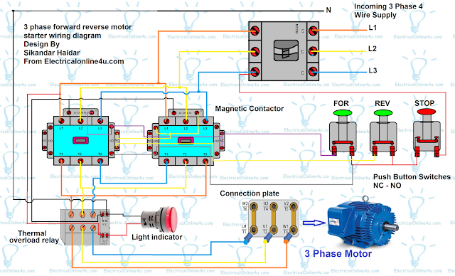
This post is about the 3 phase forward reverse motor control circuit diagram. Or how make a forward reverse 3 phase motor starter. As you know that if we change one phase with other phase, the 3 phase motor change the rotation direction. For that we use two magnetic contactors. NC and NO Switches to stop motor, to run motor forward or reverse. This can be called up down 3 phase motor starter.
3 Phase Forward Reverse Motor Control Circuit Diagram
ere I have a complete wiring diagram of 3 phase motor forward and reverse. In the diagram you can see motor main wiring and control circuit wiring. The 3 pole MCCB circuit breaker connection shown. Two magnetic contactors shown and also induction motor connection shown. A normally close push button shown which used for switch off the motor or to stop the motor. 2 normally open push button used in which one is for to run motor forward and 2nd is for to run motor reverse.
Also read
thanks a lot sir.more more grace.
hi i am naqibullah from afghanistan i am hvac
3 phase forward reverse is stimulate to all maters in Electrical body brought a knowledgeable to society,double pole miniature circuit can regulates to 2 pole its by model from manufacturer or engineer divided it