Single Phase Submersible Pump Starter Wiring Diagram
As you know that nowadays we use chose submersible pump motor on the place of other pump motor, that’s why I am writing this post about single phase submersible pump starter wiring diagram and a video tutorial which help you understood the complete wiring connection. This will be your complete guide from installing or wiring of submersible pump motor wiring connection.
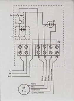
Single Phase Submersible Pump Starter Wiring Diagram
Today I open a submersible pump control box and change the change the motor capacitor because the old capacitor weakened and I replace it with new one. I saw the diagram on the back side of box which locked on my mobile by using mobile camera. Today I will share with the complete diagram of submersible pump. In submersible motor we use wire connectors, DPST switch (double pole single throw) , capacitor and reset able thermal overload protector. From the switch we can switch on or off the motor , and reset able thermal overload protect our motor during high current flow. Here is the complete diagram of single phase submersible pump starter wiring diagram below.
Single Phase Submersible Pump Motor Control box wiring Explanation video tutorial
The above diagram is a symbol diagram, here is another diagram from which you can also learn easily so for better understand or if did not understand then watch the below video tutorial. In the below video tutorial I shown another image type diagram of submersible pump control starter box which explain step by step, so for better understanding kindly watch the below single phase submersible pump starter wiring diagram explanation video tutorial in your motor language English. (note that before your start work, switch off the main circuit breaker)
I hope after watching the above single phase submersible pump starter wiring diagram guide video tutorial, I hope now you will fully understood the complete submersible pump control starter wiring diagram or installation and now you will be able to wire or make your own submersible pump motor starter, however now if you have any question regarding the video tutorial or diagram then you can ask your question by using the below comments section.
Also read:
All you do in the video is describe what the diagram shows – you don’t even begin to explain why the connections are made in that way so it is no real help to people watching it. What does the capacitor do? What you need to explain is that by wiring it the way you show in the diagram, when you switch the DPST switch on its connects the capacitor to the start coil of the pump to give a torque boost for starting it, and then once it is running the run coil takes over. The overload switch is there so that if the pump gets too hot the current through the run coil will increase, tripping the overload and cutting out the power to the pump. You don’t explain any of that but you should do – it is no good just knowing what to do – you also have to know why you do it!